41 minutes read | published @ August 27, 2021
Let’s build an LC-3 Virtual Machine
Virtual Machines (VMs) are a magical thing: a computer being emulated inside a physical computer. Since this emulated computer isn’t physical, we call it “virtual”. Such a simple description for something so powerful.
From a practical perspective, VMs allow users to safely run programs in an isolated environment: the emulated machine.
Why build a Virtual Machine from scratch
So, why build one when there are already so many great VMs out there? Simply put: To better understand how computers work. Personally, whenever I need to understand something complex enough that reading by itself won’t give me a deep understanding, I must build it. That which I cannot build, I cannot deeply understand.
I’ve found that learning how to build a simple VM is a great and seemingly underrated way to learn the basic philosophy behind assembly and assemblers.
Also, Justin Meiners and Ryan Pendleton already put out a great piece on building an LC-3 VM. I’m writing this document as a complement to this work. I go into a little more details and some of the underlying ideas I found tricky to understand. And as an alternative to writing an LC-3 in C, I’m doing it in Rust.
You can find the final source code here.
How to read this document
This guide is relatively long. VMs aren’t simple, and there is a lot of knowledge about it that, as I went through it, I found to be sort of “hidden,” or “heavy assumed to be known,” and that made understanding much harder for me.
For instance, I studied bitwise operations (such as shifts) a long time ago, I know the concept, but I have never had the chance to use it directly. And because of that, many tricks used in systems-level programming went straight over my head – these are “tribal” knowledge that people assume to be trivial, and therefore it is barely touched in these other documents.
I wanted to follow a different approach, a first-principles approach. I try to go over the most fundamental principles and tricks used to build a VM, with little prerequisite knowledge in systems programming other than entry-level Rust knowledge.
I’ve learned a lot along the way – systems programming is super fun. That said, let’s get to it.
The VM abstraction
The virtual machine will have two main components: registers and memory. It’s much simpler than it sounds.
Memory is where we will store a program’s binary representation; it’s a bounded array of bytes. Yup, that’s all there is to it, a good old array that will contain instructions and the indices are the addresses.
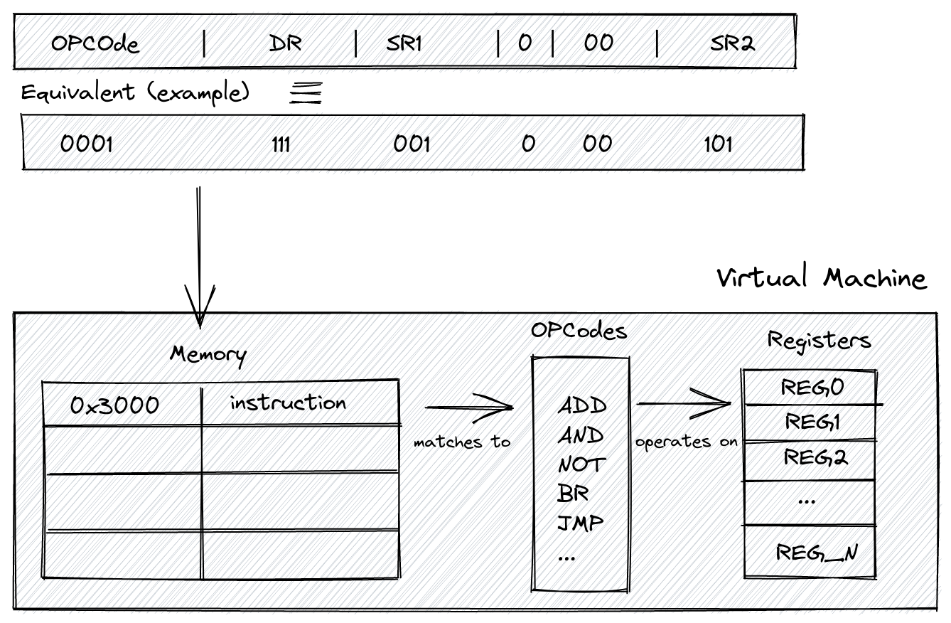
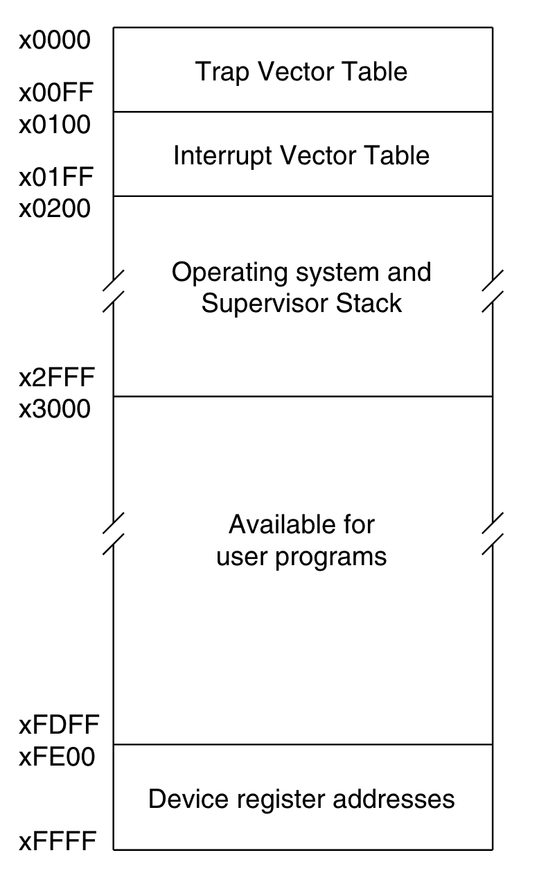
When loading an LC-3 program into memory, we do it at the address/index 0x3000 (12288 in decimal), the program section of the VM’s memory. Everything before this index is reserved for other things we’ll talk about later. Here’s the memory layout for the LC-3 memory:
Registers will store data that our opcode (Operation Code) will operate on. Physically, think of registers like a type of memory that’s much closer to the CPU than, say, the RAM.
Here we have 7 of these general-purpose registers. On top of that, we have two special purpose registers that I’ll talk about below.
Controlling the program flow with the Program Counter (PC) Register
The program counter (PC) stores the address of the next instruction in memory to be executed. In other words, it will point to an index/address in our array that represents the memory of the VM.
Manipulating this PC register is how we “walk” through each instruction and perform loops, conditional branching, and jumps; simply changing the index/address will affect the execution of the next instruction. For instance, in a loop instruction, we change the PC to go back a few “steps” until we meet a specific condition.
But how do we check for these logical conditions? Enters our next special purpose register.
Checking for logical conditions with the Condition Flags (Cond) Register
And talking about conditions brings us to the next special register: The condition flags register that tells us about the last computation. This register checks for conditions to perform control flow tasks (loops, ifs, etc.). It’s a straightforward one, and it might not immediately make sense how we use it, but all it does is store the signal (negative, zero, or positive) status of the last operation that happened within the machine. We’ll go over it in more detail later!
Structuring the project
This is how I’m structuring the project:
LC_3 git:(master) ✗ tree src
src
├── hardware
│   ├── instruction
│   │   └── mod.rs // Instruction-related code
│   ├── mod.rs // Glue-code for all the virtual hardware
│   ├── register
│   │   └── mod.rs // Register-related code
│   └── vm
│       └── mod.rs // High-level VM-related code (uses the registers/instruction)
└── main.rs
This is dead simple to represent in Rust; In src/hardware/register/mod.rs we have the abstraction for our registers:
pub struct Registers {
    pub r0: u16,
    pub r1: u16,
    pub r2: u16,
    pub r3: u16,
    pub r4: u16,
    pub r5: u16,
    pub r6: u16,
    pub r7: u16,
    pub pc: u16,
    pub cond: u16,
}

impl Registers {
    pub fn new() -> Registers {
        Registers {
            r0: 0,        // general purpose register
            r1: 0,        // general purpose register
            r2: 0,        // general purpose register
            r3: 0,        // general purpose register
            r4: 0,        // general purpose register
            r5: 0,        // general purpose register
            r6: 0,        // general purpose register
            r7: 0,        // general purpose register
            pc: PC_START, // program counter
            cond: 0,      // condition flag
        }
    }

    pub fn update(&mut self, index: u16, value: u16) {
        match index {
            0 => self.r0 = value,
            1 => self.r1 = value,
            2 => self.r2 = value,
            3 => self.r3 = value,
            4 => self.r4 = value,
            5 => self.r5 = value,
            6 => self.r6 = value,
            7 => self.r7 = value,
            8 => self.pc = value,
            9 => self.cond = value,
            _ => panic!("Index out of bound"),
        }
    }

    pub fn get(&self, index: u16) -> u16 {
        match index {
            0 => self.r0,
            1 => self.r1,
            2 => self.r2,
            3 => self.r3,
            4 => self.r4,
            5 => self.r5,
            6 => self.r6,
            7 => self.r7,
            8 => self.pc,
            9 => self.cond,
            _ => panic!("Index out of bound. "),
        }
    }
}
Notice how we’re initializing the PC as: pc: PC_START,, where PC_START is 0x3000. That’s because, as we’ve seen in the specs, this is where the space in the VM’s memory reserved for the user’s program starts.
Also, notice that we’re explicitly using u16 (unsigned 16 bits) instead of the usual u8. We’ll talk about this soon enough!
Then, for our condition flag register, its goal is to store the information about the latest computation, which we will then use to test logical conditions. It’s a simple Enum, but it contains some tricks:
enum ConditionFlag {
    POS = 1 << 0, // Positive
    ZRO = 1 << 1, // Zero
    NEG = 1 << 2, // Negative
}
The << operator is a left bit shift operator. It’s simpler than it looks: n << k means we’re moving (or shifting) the bits in the binary representation of the number n by k. for instance, 1 in binary representation is 0000000000000001.
1 << 2 means we’re shifting the bits twice to the left so that the 1 at the end of 0000000000000001 will effectively move to the left, twice. It ends up being 0000000000000100, which in decimal representation is 4. Thus, 1 << 2 == 4. So why are we storing 1, 2, 4 here? Glad you asked. In binary, with 3 bits only:
1 == 0012 == 0104 == 100
So we’re playing with the possible conditional flags settings! Because the condition instruction will be nzp (neg, zero, pos) and only one can be set at a time, it will either be 001 (positive set nz1) 010 (zero set, n1p) 100 (negative set, 1zp). And these three binary values are 1, 2, and 4 in decimal base. How cool is that?!
Now we’ve gotta add one more method to our Registers implementation: one to update the condition register based on the last operation on a given (general purpose) register:
pub fn update_r_cond_register(&mut self, r: u16) {
    if self.get(r) == 0 {
        // Note that `9` is the register number 9,
        // which is the cond register
        self.update(9, ConditionFlag::ZRO as u16);
    } else if (self.get(r) >> 15) != 0 {
        // a 1 in the left-most bit indicates negative
        self.update(9, ConditionFlag::NEG as u16);
    } else {
        self.update(9, ConditionFlag::POS as u16);
    }
}
What does the LC-3 compiled binary look like?
Now that we have the skeleton of our VM’s abstraction somewhat ready, let’s take a step back and see how an LC-3 compiled binary looks like.
Under examples/ we have an already compiled hello_world program for the LC-3. Let’s try reading it and seeing what it looks like:
let data = fs::read(args[1].clone()).expect("Unable to read file");

println!("data: {:?}\n", data);
Output:
data: [48, 0, 224, 2, 240, 34, 240, 37, 0, 72, 0, 101, 0, 108, 0, 108, 0, 111, 0, 32, 0, 87, 0, 111, 0, 114, 0, 108, 0, 100, 0, 33, 0, 0]
As expected: gibberish.
Okay, so, quickly taking a look at the fs::read docs we see that its signature is: pub fn read<P: AsRef<Path>>(path: P) -> io::Result<Vec<u8>> meaning, it returns a vector of 8 bits.
However, LC-3 operates with 16 bits per instruction!
We have to change how we’re reading the file to read it expecting 16 bits instead of 8.
Let’s see how the human-readable hello world program in LC-3 assembly looks like:
.ORIG x3000                        ; this is the address in memory where the program will be loaded
LEA R0, HELLO_STR                  ; load the address of the HELLO_STR string into R0
PUTs                               ; output the string pointed to by R0 to the console
HALT                               ; halt the program
HELLO_STR .STRINGZ "Hello World!"  ; store this string here in the program
.END                               ; mark the end of the file
The first line (.ORIG x3000) means that the first 16 bits read from the compiled binary tell the VM the position in memory where the program starts.
Back to reading and loading the compiled binary, but now expecting u16 instead of u8:
// Note the `read_u16`, forcing it to read as u16 and not u8.
let base_address = f.read_u16::<BigEndian>().expect("error");

let mut address = base_address as usize;
loop {
    match f.read_u16::<BigEndian>() {
        Ok(instruction) => {
            println!("address: {:?} instruction: {:?}\n", address, instruction);
            address += 1;
        }
        Err(e) => {
            if e.kind() == std::io::ErrorKind::UnexpectedEof {
                println!("OK")
            } else {
                println!("failed: {}", e);
            }
            break;
        }
    }
}
Endianness
Note that when we’re reading the 16 bits chunks, we tell Rust we want it as BigEndian: f.read_u16::<BigEndian>().
Without diving too deep into it, endianness is the order or direction in which the “machine” reads binary data. You can either read from left to right or right to left. The order is specific only to byte ordering and not bit ordering.
For instance, if we have only one byte, 0000 0010 (2 in decimal), it will be the same in big-endian or little-endian. However, the ordering is affected once we have more than 1 byte.
Big-endian means we’re storing the “big end” first, then the rest. Little-endian means storing the “little end” first. This big/little end thing means the most significant byte, the byte in a binary value that holds the biggest position.
In 00000010 (2), the left-most zero is the most significant one; changing it to 1 would cause the most significant change to the number, it would turn it into 10000010, which is 130 in decimal.
Changing the right-most zero would cause the smallest change to the number: 00000011 is 3.
Let’s consider a large 2 bytes number: 65,535, in binary: 1111 1111.
Since here we have two bytes, one is the most significant, the other is the least significant:
MSB  LSB
1111 1111
And now we reach the crux of this Big Endian vs. Little Endian understanding: Big Endian will first store the Most Significant Byte (MSB). Little Endian will store the Least Significant Byte (LSB) first.
Different machines, languages, implementations will use different endianness; such is life. LC-3 uses Big Endianness. That’s why we’re using f.read_u16::<BigEndian>().
Now let’s go back to the code above.
Running the code above passing the hello world binary file:
address: 12288 instruction: 57346
address: 12289 instruction: 61474
address: 12290 instruction: 61477
address: 12291 instruction: 72
address: 12292 instruction: 101
address: 12293 instruction: 108
address: 12294 instruction: 108
address: 12295 instruction: 111
address: 12296 instruction: 32
address: 12297 instruction: 87
address: 12298 instruction: 111
address: 12299 instruction: 114
address: 12300 instruction: 108
address: 12301 instruction: 100
address: 12302 instruction: 33
address: 12303 instruction: 0
Note that it’s showing 12288 as the base address, 12288 in hex is 0x3000, exactly how it’s in the original specs for the LC-3; how cool is that?!
We have to load the instruction 57346 in memory at the index 12288, 61474 at 12289, and so on.
Do you want to see something even cooler? In the hello world assembly, the first instruction is
LEA R0, HELLO_STR ; load the address of the HELLO_STR string into R0 PUTs
LEA (we’ll see what that is later) is the name of the instruction/opcode, let’s see the binary representation of that instruction in the spec:

Note that the OpCode is 1110.
Let’s see the output of our println! again:
address: 12288 instruction: 57346
So, load at 12288 (0x3000 in hex) the instruction 57346, this instruction in binary: 1110000000000010. Hey! The opcode is right there: 1110 000000000010.
The rest of the binary is the necessary information to perform the LEA operation, but you see that the OpCode is there. How cool is that?!
Now we have to load all these instructions coming from a program into the VM memory:
pub struct VM {
    pub memory: [u16; MEMORY_SIZE],
    pub registers: Registers,
}

impl VM {
    pub fn new() -> VM {
        VM {
            memory: [0; MEMORY_SIZE],
            registers: Registers::new(),
        }
    }

 pub fn write_memory(&mut self, address: usize, value: u16) {
        self.memory[address] = value;
    }
}
Note that we’re using a constant MEMORY_SIZE that we’re defining below. This constant is the maximum amount of memory we’re giving to our VM. We’ll be defining it as 65535, which is the max value for 16 bits.
And then our main.rs looks like this
let base_address = f.read_u16::<BigEndian>().expect("error");

// Here we're loading the program in memory
let mut address = base_address as usize;
loop {
    match f.read_u16::<BigEndian>() {
        Ok(instruction) => {
            vm.write_memory(address, instruction);
            address += 1;
        }
        Err(e) => {
            if e.kind() == std::io::ErrorKind::UnexpectedEof {
                println!("OK")
            } else {
                println!("failed: {}", e);
            }
            break;
        }
    }
}
In plain English: we start at the base address 0x3000, load the first instruction at this position, increment the address, load the next instruction, and so on.
Executing the program
Once we have a program loaded into the VM’s memory, running it is a matter of walking through the memory positions using the value stored in the Program Counter (PC) register.
use vm::VM;

pub const MEMORY_SIZE: usize = std::u16::MAX as usize;

pub fn execute_program(vm: &mut VM) {
    while vm.registers.pc < MEMORY_SIZE as u16 {
        // Read instruction
        let instruction = vm.read_memory(vm.registers.pc);

        // Increment program counter
        vm.registers.pc += 1;

        // Extract op_code and execute operation
        instruction::execute_instruction(instruction, vm)
    }
}
This leads to two important functions: read_memory and execute_instruction.
Reading the memory is pretty straightforward, at least at this stage:
pub fn read_memory(&mut self, address: u16) -> u16 {
 self.memory[address as usize]
}
Executing the instruction is about:
- Detecting which instruction a given
u16value is, i.e., what’s the OpCode? - Matching it against all possible OpCodes
- Running the matching OpCode and extracting the operands from the whole instruction.
The first two parts are pretty simple:
pub fn execute_instruction(instr: u16, vm: &mut VM) {
    // Extract OpCode from the instruction
    let op_code = get_op_code(&instr);

    // Match OpCode and execute instruction
    match op_code {
        Some(OpCode::ADD) => add(instr, vm),
        Some(OpCode::AND) => and(instr, vm),
        Some(OpCode::NOT) => not(instr, vm),
        Some(OpCode::BR) => br(instr, vm),
        Some(OpCode::JMP) => jmp(instr, vm),
        Some(OpCode::JSR) => jsr(instr, vm),
        Some(OpCode::LD) => ld(instr, vm),
        Some(OpCode::LDI) => ldi(instr, vm),
        Some(OpCode::LDR) => ldr(instr, vm),
        Some(OpCode::LEA) => lea(instr, vm),
        Some(OpCode::ST) => st(instr, vm),
        Some(OpCode::STI) => sti(instr, vm),
        Some(OpCode::STR) => str(instr, vm),
        Some(OpCode::TRAP) => trap(instr, vm),
        _ => {}
    }
}
Note that each OpCode is incredibly well specified in the original spec docs. Our goal is to implement one by one!
Extracting and handling our first instruction
Okay, how do we know which instruction is a u16 piece of data?
Let’s consider the first assembly instruction in our hello world program: LEA, it has, as expected, 16 bits:

And we want to take an instruction, grab the first 4 bits (the OpCode) and confirm it’s an LEA OpCode: 1110. Given the first instruction, if we print its decimal and binary representation, we get:
println!("instruction: {:?}\n", instruction);
println!("instruction in binary: {:#b}\n", instruction);
Output:
instruction: 57346
instruction in binary: 0b1110000000000010
Okay, so the OpCode is right there: 1110, how do we extract it from the whole instruction?
A common technique is to use bit shifting (>> or <<) to turn 1110000000000010 into 0000000000001110, which is the OpCode representation with the full leading zeroes!
That means we can right-shift the original number 12 times by using >>. Go on, count, and you will see that moving each element in that binary representation from its original position (1110000000000010) to the right, 12 times, will lead to 0000000000001110.
So if we do this:
println!("instruction: {:?}\n", instruction);

println!("instruction in binary: {:#b}\n", instruction);

println!("instruction >> 12: {:?}\n", instruction >> 12);

println!("instruction >> 12: {:#b}\n", instruction >> 12);
We get:
instruction: 57346

instruction in binary: 0b1110000000000010

instruction >> 12: 14

instruction >> 12: 0b1110
Now, here are all the OpCodes from the specs:
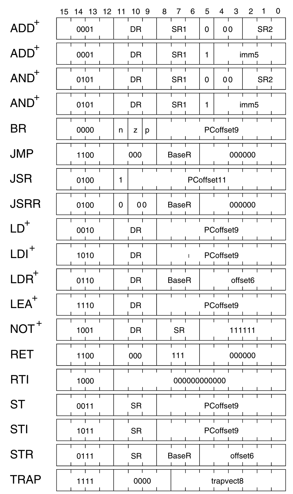
We now have to match the extracted 4 first bits of an instruction against the list of all OpCodes:
pub enum OpCode {
    BR = 0, // branch
    ADD,    // add
    LD,     // load
    JSR,    // jump register
    AND,    // bitwise and
    LDR,    // load register
    STR,    // store register
    RTI,    // unused
    NOT,    // bitwise not
    LDI,    // load indirect
    STI,    // store indirect
    JMP,    // jump
    RES,    // reserved (unused)
    LEA,    // load effective address
    TRAP,   // execute trap
}

pub fn get_op_code(instruction: &u16) -> Option<OpCode> {
    match instruction >> 12 {
        0 => Some(OpCode::BR),
        1 => Some(OpCode::ADD),
        2 => Some(OpCode::LD),
        3 => Some(OpCode::ST),
        4 => Some(OpCode::JSR),
        5 => Some(OpCode::AND),
        6 => Some(OpCode::LDR),
        7 => Some(OpCode::STR),
        8 => Some(OpCode::RTI),
        9 => Some(OpCode::NOT),
        10 => Some(OpCode::LDI),
        11 => Some(OpCode::STI),
        12 => Some(OpCode::JMP),
        13 => Some(OpCode::RES),
        14 => Some(OpCode::LEA),
        15 => Some(OpCode::TRAP),
        _ => None,
    }
}
Notice that we’re matching it against the decimal representation of the instruction that’s coming as u16.
Now our execute_instruction makes a lot more sense:
pub fn execute_instruction(instr: u16, vm: &mut VM) {
    // Extract OpCode from the instruction
    let op_code = get_op_code(&instr);

    // Match OpCode and execute instruction
    match op_code {
        Some(OpCode::ADD) => add(instr, vm),
        Some(OpCode::AND) => and(instr, vm),
        Some(OpCode::NOT) => not(instr, vm),
        Some(OpCode::BR) => br(instr, vm),
        Some(OpCode::JMP) => jmp(instr, vm),
        Some(OpCode::JSR) => jsr(instr, vm),
        Some(OpCode::LD) => ld(instr, vm),
        Some(OpCode::LDI) => ldi(instr, vm),
        Some(OpCode::LDR) => ldr(instr, vm),
        Some(OpCode::LEA) => lea(instr, vm),
        Some(OpCode::ST) => st(instr, vm),
        Some(OpCode::STI) => sti(instr, vm),
        Some(OpCode::STR) => str(instr, vm),
        Some(OpCode::TRAP) => trap(instr, vm),
        _ => {}
    }
}
And if we print the op_code for each instruction coming from the hello world program, we get:
op_code: Some(LEA)

op_code: Some(TRAP)

op_code: Some(TRAP)
Now let’s continue the implementation and implement only the necessary to run the hello world program: Some(OpCode::LEA) => lea(instr, vm),
LEA stands for Load Effective Address. As we’ve seen before, the first 4 bits are the OpCode identification (1110)

The other two are the Direct Register (DR) and the Program Counter (PC) offset.
The first instruction is doing the following:
LEA R0, HELLO_STR
So, effectively, we’re loading an address into a register. In this case, we’re loading the string HELLO_STR into the register R0 by loading the address where the HELLO_STR lives.
From the original specs:
An address is computed by sign-extending bits [8:0] to 16 bits and adding this value to the incremented PC. This address is loaded into DR. The condition codes are set, based on whether the value loaded is negative, zero, or positive.
And then the footnote:
The LEA instruction does not read memory to obtain the information to load into DR. The address itself is loaded into DR.
Extracting information from a binary encoded value
So, for the LEA instruction, here’s what the code needs to do.
First, get the DR portion of the instruction:
let dr = (instruction >> 9) & 0x7;
This is a trick to get the destination register portion of the instruction.
Let’s break this down. The instruction that we’ve received at LEA R0, HELLO_STR is 0b1110_000_000000010.
From left to right: 1110 is the OpCode, 000 is the Direct Register (DR), and 000000010 is the PCOffset9.
Then when we shift it to the right 9 times, we get:
original instruction: 0b1110_000_000000010
instruction >> 9:     0b0000000001110_000
So we’ve shifted enough that the last three bits are the direct register in the instruction: 000. The bits shifted “out” of the value sorta “disappear” from the value; in other words, they don’t rotate back to the beginning of the value.
Now that we have our “target” bits aligned at the end of the value, we apply a mask & 0x7 (0b0000000000000111). This mask is a bitwise AND against the instruction that we shifted.
And the result is:
instruction >> 9 & 0x7: 0b0000000000000000
So it’s the register 0, as expected.
But why do we mask? There are usually three reasons to apply bitwise masking:
- Bitwise AND to extract a subset of the bits in the value
- Bitwise OR to set a subset of the bits in the value
- Bitwise XOR to toggle a subset of the bits in the value
In the AND case, for instance:
Mask:   0000   1111
Value:  0101   0101
-------------------
Result: 0000   0101
The goal of this mask is, from left to right, to clear the first 4 bits and keep the last 4 bits of the value. So the result will be 0b00000101.
So in our LEA R0, HELLO_STR case, (instruction >> 9) & 0x7 is trying to say: shift it so that the last three bits are the direct register we’re looking for, but since the result of that instruction >> 9 isn’t the final direct register (only the last 3 bits), mask it with 0b0000000000000111 so that we clear everything up to the last three bits, which is what we want. The resulting 16 bits value will be exactly the direct register! How cool is that?! I find the intricate simplicity behind this technique beautiful.
Sign extension
Now back to the LEA spec:
An address is computed by sign-extending bits [8:0] to 16 bits and adding this value to the incremented PC.
Let’s see how this sign-extending thing works. Simply put, because we’re operating on 16 bits, whenever a value has less than 16 bits, we have to extend it to be 16 bits.
The address we’re loading with LEA, bits 8 to 0 (left to right), clearly isn’t 16 bits – so we have to sign-extend it!
For positive numbers, it’s easy: add zeroes before the value. This doesn’t work for negative numbers, though. Borrowing an example from Justin:
For example, -1 in 5 bits is
1 1111. If we just extended it with 0’s, this is0000 0000 0001 1111, which is equal to 31
So instead of just filling in zeroes, we must also fill in ones for negative numbers. So this is how it looks:
// ...

let pc_offset = sign_extend(instruction & 0x1ff, 9);

// ...

fn sign_extend(mut x: u16, bit_count: u8) -> u16 {
    if (x >> (bit_count - 1)) & 1 != 0 {
        x |= 0xFFFF << bit_count;
    }
    x
}
More bitwise tricks! Let’s break this down.
We start off with
sign_extend(instruction & 0x1ff, 9);
0x1ff is 111111111, nine consecutive ones. Another mask! By instruction & 0x1ff, we mean to keep only the last 9 bits of the instruction, which happens to be the PCOffset9, the address we’re loading into a register, and the value that we have to sign-extend.
So here we’re just extracting the PCOffset9 portion from the instruction. We didn’t need to shift things around because PCOffset9 is already right-aligned.
Now, because it’s a 9-bit value, we want to extend it to be 16. Enters sign_extend function. Let’s break it down. You can check the formal definition for sign extension here: https://en.wikipedia.org/wiki/Sign_extension.
The short version is, if it’s a signed positive number, padding with zeroes will work. Adding zeroes won’t preserve the value if it’s a signed negative number, but padding with ones will.
The sign_extend is doing that. It takes a bit_count which is the number of bits in the original value; in the case of the LEA command, we’re dealing with a 9-bit value that we want to convert into 16-bit. That’s why we call it like this: let pc_offset = sign_extend(instruction & 0x1ff, 9);
The if clause if (x >> (bit_count - 1)) & 1 != 0 is testing the sign of the value. We’re moving x to the right up until the sign bit (bit_count - 1) and applying a single bitmask & 1 to grab it. Then check if it’s different than zero; if it is, it’s signed as 1 (negative), meaning we have to pad with ones instead of zeroes. Otherwise, it’s zero, and we return as is, as it already is padded with zeroes.
And the part where we pad with ones is:
x |= 0xFFFF << bit_count;
This part is tricky if you’re new to bitwise operations. 0xFFFF << bit_count is happening, then its result is |="d against x. |= means bitwise OR, but with an assignment step, so x will be OR’d against the result of 0xFFFF << bit_count and the result of that OR will be assigned to x, replacing the original value.
0xFFFF is 1111111111111111 (16 bits). We shift it left bit_count times, i.e., the number of bits in the original value x (in this case,9). Meaning that, for the original value, we’re going to “leave it alone” and only set 1’s to the rest, all the way to 16 bits total. This way, we’re going to have 1111111_<original x value>, and we’re done! Super clever trick.
Effectively, the LEA command in our hello world example is loading the address of the beginning of the string onto the register 0.
The last part is updating the cond register based on the value stored in the register that we last operated on, in this case, R0. Which looks like
vm.registers.update_r_cond_register(dr);

// ...

pub fn update_r_cond_register(&mut self, r: u16) {
    if self.get(r) == 0 {
        self.update(9, ConditionFlag::ZRO as u16);
    } else if (self.get(r) >> 15) != 0 {
        // a 1 in the left-most bit indicates negative
        self.update(9, ConditionFlag::NEG as u16);
    } else {
        self.update(9, ConditionFlag::POS as u16);
    }
}

enum ConditionFlag {
    POS = 1 << 0, // Positive
    ZRO = 1 << 1, // Zero
    NEG = 1 << 2, // Negative
}
Then, in our hello world example, we run a TRAP OpCode. Trap is an OpCode for interacting with IO devices, such as halting, output/input of data, etc. In other words, it’s where we go to do a very known thing called system calls!
The trap spec is unique in comparison to the other OpCodes:
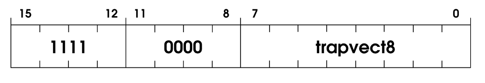
1111 is the OpCode identifier, but then we have this thing called a trap vector, which is 8 bits long. The trap vector holds the identifier to which system call it wants to execute. The spec is super clear about how it works:
trapallows interacting with I/O devices. First R7 is loaded with the incremented PC. (This enables a return to the instruction physically following the TRAP instruction in the original program after the service routine has completed execution.) Then the PC is loaded with the starting address of the system call specified by trap vector8. The starting address is contained in the memory location whose address is obtained by zero-extending trap vector8 to 16 bits.
And then below:
Memory locations x0000 through x00FF, 256 in all, are available to contain starting addresses for system calls specified by their corresponding trap vectors. This region of memory is called the Trap Vector Table.
And below that we have the list of all “trap service routines”:
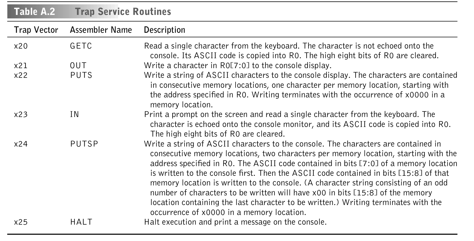
So our trap implementation will look like something like this
pub fn trap(instruction: u16, vm: &mut VM) {
    println!("trap instruction: {:#018b}\n", instruction);

    match instruction & 0xFF {
        0x20 => {
            // Get character
        }
        0x21 => {
            // Write out character
        }
        0x22 => {
            // Puts
        }
        0x23 => {
            // In, Print a prompt on the screen and read a single character from the keyboard. The character is echoed onto the console monitor, and its ASCII code is copied into R0.The high eight bits of R0 are cleared.
        }
        0x24 => {
            // Putsp
        }
        0x25 => {
   // Halt
        }
        _ => {
            process::exit(1);
        }
    }
}
And just like the “higher level” OpCodes (LEA, ADD, etc.), we have to implement one by one.
In our hello world example, the first trap used is PUTS, to print a string. The instruction binary representation is: 1111000000100010. So, 00100010 (the last 8 bits) is the trap vector identifier. 00100010 is 0x22 in hex, which maps to PUTS!
Notice that we do a match instruction & 0xFF { to find 0x22. Just like before, we do the & 0xFF (called a mask) to capture only the 0xFF worth of bits from the instruction, 0xFF is 11111111, 8 bits, which is the length of the trap vector we want to capture.
Here’s how the PUTS implementation looks like
x22 => {
 // Puts
 let mut index = vm.registers.r0;

 let mut c = vm.read_memory(index);

 while c != 0x0000 {
     print!("{}", (c as u8) as char);
     index += 1;
     c = vm.read_memory(index);
 }

 io::stdout().flush().expect("failed to flush");
}
We’re printing char by char, and the address of the beginning of the string lives in the register 0. So we’re walking through it.
Let’s visualize this better. If we print instruction:address pairs at the beginning, when we’re loading the hello world program into the VM’s memory, we see this:
address: 12288 instruction: 57346
address: 12289 instruction: 61474
address: 12290 instruction: 61477
address: 12291 instruction: 72
address: 12292 instruction: 101
address: 12293 instruction: 108
address: 12294 instruction: 108
address: 12295 instruction: 111
address: 12296 instruction: 32
address: 12297 instruction: 87
address: 12298 instruction: 111
address: 12299 instruction: 114
address: 12300 instruction: 108
address: 12301 instruction: 100
address: 12302 instruction: 33
address: 12303 instruction: 0
Notice how at the beginning of the address 12291 the instructions become slightly different. This is where the characters of the "hello world" string start being loaded at. Fun detail: these “instructions” start to look like utf8 encoding!
Let’s further confirm that 12291 is the beginning of the string:
let mut index = vm.registers.r0;
println!("index: {:?}\n", index);
index: 12291
Alright! Once we understand that, the reading loop becomes trivial:
while c != 0x0000 {
    print!("{}", (c as u8) as char);
    index += 1;
    c = vm.read_memory(index);
}
We’re just walking through each address until we see a 0x0000. And the print! over there is printing it to the stdout, that’s how we see Hello, world! coming from the register 0!
Then, the next trap instruction we see is HALT, 1111000000100101. Which is the simplest one to implement:
0x25 => {
    println!("HALT detected");
    io::stdout().flush().expect("Failed to flush");
    process::exit(1);
}
And that’s it for the hello world example:
  Finished dev [unoptimized + debuginfo] target(s) in 0.19s
     Running `target/debug/LC-3 examples/hello-world.obj`
OK
Hello World!HALT detected
We just managed to run a binary file for the LC-3 computer in our VM!
Now, our next goal is to implement the rest of the OpCodes, add some more keyboard input control, and then we’ll be good to run more complex programs. It might sound complicated, but it isn’t. Now that we understand the logic and flow behind this VM, its bitwise operation tricks, how we use registers, etc., it’s now a matter of reading the spec for each OpCode and implementing its logic, which is usually very straightforward.
Implementing the ADD OpCode
Here’s the ADD spec:
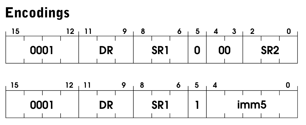
We have two operation modes for ADD, and we can pick which one we’re gonna use by setting the bit [5] of the instruction. Here’s how it’s officially described:
If bit [5] is 0, the second source operand is obtained from SR2. If bit [5] is 1, the second source operand is obtained by sign-extending the imm5 field to 16 bits. In both cases, the second source operand is added to the contents of SR1 and the result stored in DR. The condition codes are set, based on whether the result is negative, zero, or positive
In other words, ADD will be adding two numbers; the first comes from a register, the second will come either from a register (SR2) or by directly passing an immediate value to the instruction, like:
ADD R2, R3, R4 ; R2←R3+R4, R2 receives the sum of what's in R3 and R4
ADD R2, R3, #7 ; R2←R3+7, R2 receives the sum of what's in R3 and the num 7
In the immediate case, it needs to be in 16 bits because it’s a full value, so we sign-extend it. The trade-off is that the instruction only has room for a small number, up to 2^5=32.
Here’s how the code looks like
pub fn add(instruction: u16, vm: &mut VM) {
    let dr = (instruction >> 9) & 0x7;

    // First operand
    let sr1 = (instruction >> 6) & 0x7;

    // Check if we're in immediate mode or register mode.
    let imm_flag = (instruction >> 5) & 0x1;
    if imm_flag == 1 {
        let imm5 = sign_extend(instruction & 0x1F, 5);
        //val is declared as u32 to prevent from overflow.
        let val: u32 = imm5 as u32 + vm.registers.get(sr1) as u32;
        //val is declared as u16, so that type arithmatic kick in and number is rounded to get fit into u16.
        vm.registers.update(dr, val as u16);
    } else {
        /* first operand (SR2) */
        let sr2 = instruction & 0x7;
        let val: u32 = vm.registers.get(sr1) as u32 + vm.registers.get(sr2) as u32;
        vm.registers.update(dr, val as u16);
    }

    vm.registers.update_r_cond_register(dr);
}
Let’s break it down.
let dr = (instruction >> 9) & 0x7;
This gets the destination address using bitwise operation tricks.
instruction >> 9 will shift the binary from the instruction it 9 times to the right.
That means the last bit will be the end of the DR portion of the instruction.
And the bitwise-and (&) 0x7 will grab only the length of 111 out of the instruction, i.e., the last 3 bits, which is precisely the length of the DR.
let sr1 = (instruction >> 6) & 0x7;
Same thing as before, but now we’re moving only 6 times because the SR1 register is after the direct register (DR).
let imm_flag = (instruction >> 5) & 0x1;
Again, same thing, just the one bit at position 5 that represents the operation mode.
Then we proceed with the operation mode logic:
if imm_flag == 1 {
    let imm5 = sign_extend(instruction & 0x1F, 5);

    // This is declared as u32 to prevent from overflow.
    let val: u32 = imm5 as u32 + vm.registers.get(sr1) as u32;

    // Set the result of the sum to the target register
    vm.registers.update(dr, val as u16);
} else {
    // If not immediate mode, we need to extract the second register.
    let sr2 = instruction & 0x7;

    // Proceed as usual
    let val: u32 = vm.registers.get(sr1) as u32 + vm.registers.get(sr2) as u32;

    // Set the result of the sum to the target register
    vm.registers.update(dr, val as u16);
}
If it’s the immediate mode, grab the immediate value by extending it to be 16 bits. Then add and update the target register (R0).
If not immediate mode, grab the other register passed in the instruction and proceed as usual.
And that’s it! Then we have to update the condition register:
vm.registers.update_r_cond_register(dr);
We pass dr here because this is the register containing the result of the last operation. Remember that the cond register’s idea is to set positive/negative/zero based on the result of the last operation, which in this case live in dr.
Implementing the LDI OpCode

In simple terms, the LDI operation is loading the address of a piece of data onto a register. However, it’s a bit trickier than that because it adds another layer of indirection (that’s why it’s called load indirect).
It starts by adding the PC to a PCOffset9 in the instruction. This sum is an address to a memory location, and that address contains another value which is the address of the value to load. It sounds tricky, but the code probably makes it clear. It looks like this:
pub fn ldi(instruction: u16, vm: &mut VM) {
    // Get the direct register encoded in the instruction (see `add` fn for more in-depth details)
    let dr = (instruction >> 9) & 0x7;

    // Get the PC offset and sign extend it to be 16 bits
    let pc_offset = sign_extend(instruction & 0x1ff, 9);

    let first_read = vm.read_memory(vm.registers.pc + pc_offset);

    let resulting_address = vm.read_memory(first_read);

    vm.registers.update(dr, resulting_address);
    vm.registers.update_r_cond_register(dr);
}
Implementing the AND OpCode
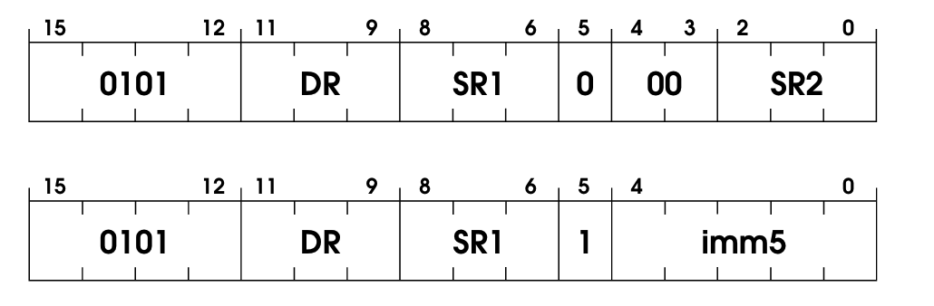
Good old logical and, but applied to binary values. This one is similar to ADD; it has two operation modes: immediate and register. Since you probably already got the hang of it, here’s the code without much explanation:
pub fn and(instruction: u16, vm: &mut VM) {
    // Get the direct register encoded in the instruction (see `add` fn for more in-depth details)
    let dr = (instruction >> 9) & 0x7;

    // As seen in `add` fn, same tricks.
    let sr1 = (instruction >> 6) & 0x7;
    let imm_flag = (instruction >> 5) & 0x1;

    if imm_flag == 1 {
        let imm5 = sign_extend(instruction & 0x1F, 5);
        // Perform the bitwise and (`&`) and store its value in the DR.
        vm.registers.update(dr, vm.registers.get(sr1) & imm5);
    } else {
        let sr2 = instruction & 0x7;
        // Perform the bitwise and (`&`) and store its value in the DR.
        vm.registers
            .update(dr, vm.registers.get(sr1) & vm.registers.get(sr2));
    }

    vm.registers.update_r_cond_register(dr);
}
Nothing new here, same old tricks, but instead of +ing stuff, we’re just bitwise-and’ing it.
Implementing the NOT OpCode
 Another dead simple OpCode, simple binary negation. Won’t bore you with the details:
pub fn not(instruction: u16, vm: &mut VM) {
    let dr = (instruction >> 9) & 0x7;
    let sr1 = (instruction >> 6) & 0x7;
    vm.registers.update(dr, !vm.registers.get(sr1));

    vm.registers.update_r_cond_register(dr);
}
Implementing the BR OpCode
Finally, we’re using the condition register! We use a branch (BR) operation to control the flow of a program. There are many ways to use it:
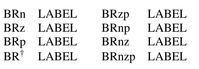
Let’s look at the instruction encoding:

This one has some tricks that are worth digging into.
We have three bits set here: n for negative, z for zero, and p for positive. If any of these conditions are true, we’ll move the flow of the program to wherever LABEL is, which is a position stored in the PC register.
In a more concrete example, if the BR instruction has 101 for nzp, we’re saying that if the last instruction resulted in a negative number of a positive number, but not zero, then we trigger the branching, by moving the PC to LABEL.
This brings us to how we implement the condition flags in our VM:
enum ConditionFlag {
    POS = 1 << 0, // Positive
    ZRO = 1 << 1, // Zero
    NEG = 1 << 2, // Negative
}
Simple enough, but why these values set for POS, ZRO, and NEG?
1 in binary representation is 0000000000000001, 1 << 2 means we’re shifting the bits twice to the left, so that 1 at the end will effectively move to left twice. It ends up being 0000000000000100, which in decimal representation is 4. Thus, 1 << 2 == 4.
So why are we storing 1, 2, 4 here? Glad you asked. In binary, with 3 bits only:
1 == 001
2 == 010
4 == 100
So we’re playing with the possible conditional flags settings! Because the condition instruction will be nzp (neg, zero, pos) and only one can be set at a time, it will either be:
001(positive setnz1)010(zero set,n1p)100(negative set,1zp)
And these three binary values are 1, 2, and 4 in decimal!
Now, our branching operation looks like this:
pub fn br(instruction: u16, vm: &mut VM) {
    // Grab the PCOffset of the instruction and sign extend it
    // You can read more sign extension inside the `sign_extend` fn.
    let pc_offset = sign_extend((instruction) & 0x1ff, 9);

    // Shift 9 and grab 3 bits (& 0x7 is doing that)
    // You can read more about this trick inside `lea` fn.
    let cond_flag = (instruction >> 9) & 0x7;

    if cond_flag & vm.registers.cond != 0 {
        let val: u32 = vm.registers.pc as u32 + pc_offset as u32;
        vm.registers.pc = val as u16;
    }

    // If the branch isn't taken (no condition met), PC isn't changed
    // and PC will just point to the next sequential instruction.
}
And we do the testing there as: f cond_flag & vm.registers.cond != 0 {
We’re taking the 001, or 010, or 100 stored in the condition register and &ing it to the 001, or 010, or 100 coming from the instruction; note that the one coming from the instruction can be 110, 111 or any combination.
For example, if the last operation turned positive, we have 001 in the condition register. If the condition to trigger the branching is 011 (either positive or zero), then 001 & 011 will be 001, which means the branching is enabled, meaning we will change the PC by adding the PCOffset to it and moving on. The next instruction executed will be decided by this new PCOffset; this is usually used for while/for loops and if-statements.
Implementing the JMP OpCode
JMP is another flow control operation, like BR, but without conditions. So we’re mutating the PC register no matter what.
The program unconditionally jumps to the location specified by the content of the base register in the instruction. Bits [8:6] identify the base register.
RET is listed as a separate instruction in the specification since it is a different keyword in assembly. However, it is a particular case of JMP. RET happens whenever R1 is 7.
This is how the encoding looks like:
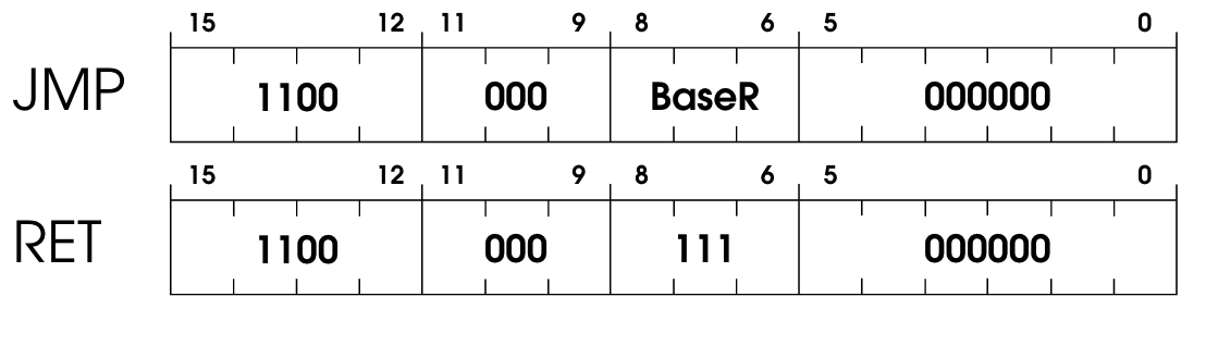
In our implementation, RET and JMP are going to be handled by the same JMP function, as they’re basically the same, just different assembly keywords, and RET is always when the register is 111 (register 7) instead of an arbitrary register BaseR..
pub fn jmp(instruction: u16, vm: &mut VM) {
    // base_reg will either be an arbitrary register or the
    // register 7 (`111`) which in this
    // case it would be the `RET` operation.
    let base_reg = (instruction >> 6) & 0x7;
    vm.registers.pc = vm.registers.get(base_reg);
}
Implementing the JSR OpCode
Also known as JumptoSubRoutine. The spec itself for this one is incredibly clear:
First, the incremented PC is saved in R7. This is the linkage back to the calling routine. Then the PC is loaded with the address of the first instruction of the subroutine, causing an unconditional jump to that address. The address of the subroutine is obtained from the base register (if bit [11] is 0), or the address is computed by sign-extending bits [10:0] and adding this value to the incremented PC (if bit [11] is 1).
The code, then, is pretty straightforward:
pub fn jsr(instruction: u16, vm: &mut VM) {
    // Grab the base register
    let base_reg = (instruction >> 6) & 0x7;

    // 0x7ff == 11111111111 (11 ones, exactly the length of PCOffset11)
    // Grab it and extend it to 16 bits.
    let long_pc_offset = sign_extend(instruction & 0x7ff, 11);

    // Grab the flag bit at [11] and test it
    let long_flag = (instruction >> 11) & 1;

    // Save the incremented PC in R7
    vm.registers.r7 = vm.registers.pc;

    if long_flag != 0 {
        // JSR case, the address to jump is computed from PCOffset11
        let val: u32 = vm.registers.pc as u32 + long_pc_offset as u32;
        vm.registers.pc = val as u16;
    } else {
        // JSRR case, address to jump to lives in the base register
        vm.registers.pc = vm.registers.get(base_reg);
    }
}
Implementing the LD OpCode
The standard load operation. Incredibly simple one!

We’re loading onto a register DR the value stored in a place in memory computed using the PCOffset9.
pub fn ld(instruction: u16, vm: &mut VM) {
    // Get the direct register encoded in the instruction (see `add` fn for more in-depth details)
    let dr = (instruction >> 9) & 0x7;

    // Grab the PCOffset and sign extend it
    let pc_offset = sign_extend(instruction & 0x1ff, 9);

    let mem: u32 = pc_offset as u32 + vm.registers.pc as u32;

    // Read the value from the place where the memory above was computed
    let value = vm.read_memory(mem as u16);

    // Save that value to the direct register and update the condition register
    vm.registers.update(dr, value);
    vm.registers.update_r_cond_register(dr);
}
Implementing the LDR OpCode
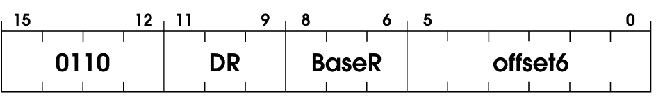 It stands for Load Base+Offset; it’s a specialized version of the
 LD operation. The only difference is that instead of only using a base register, we add the base register to an Offset6 (sign-extended to 16 bits) before loading.
pub fn ldr(instruction: u16, vm: &mut VM) {
    // Get the direct register encoded in the instruction (see `add` fn for more in-depth details)
    let dr = (instruction >> 9) & 0x7;

    // Grab the base register
    let base_reg = (instruction >> 6) & 0x7;

    // Grab the offset6 and sign extend it
    let offset = sign_extend(instruction & 0x3F, 6);

    // Compute the memory location to be loaded
    let val: u32 = vm.registers.get(base_reg) as u32 + offset as u32;

    // Read the value at that memory location
    let mem_value = vm.read_memory(val as u16).clone();

    // Update the register with the loaded value and update the condition register
    vm.registers.update(dr, mem_value);
    vm.registers.update_r_cond_register(dr);
}
Implementing the ST OpCode

Another simple operation: Store. It will store the contents in the register SR in the memory location computed by the current PC and the PCOffset9. As usual, the offset will be sign-extended to 16-bit.
The code for it is as easy as the description:
pub fn st(instruction: u16, vm: &mut VM) {
    // Get the direct register encoded in the instruction (see `add` fn for more in-depth details)
    let sr = (instruction >> 9) & 0x7;

    // Grab the PC offset and sign extend it
    let pc_offset = sign_extend(instruction & 0x1ff, 9);

    // Add the current PC to the PC offset
    // We're doing these conversions to avoid overflow
    let val: u32 = vm.registers.pc as u32 + pc_offset as u32;
    let val: u16 = val as u16;

    // Store the value in the register being passed in the instruction at
    // the address computed above
    vm.write_memory(val as usize, vm.registers.get(sr));
}
Implementing the STI OpCode
Store indirect, just like STORE, but with a layer of indirection. The encoding is very similar, though:

This part of the official spec covers it well IMO:
What is in memory at this address is the address of the location to which the data in SR is stored
It kind of sounds like pointers, right?!
The code is pretty much the same as ST (Store) with one extra step:
pub fn sti(instruction: u16, vm: &mut VM) {
    // Get the direct register encoded in the instruction (see `add` fn for more in-depth details)
    let sr = (instruction >> 9) & 0x7;

    // Grab the PC offset and sign extend it
    let pc_offset = sign_extend(instruction & 0x1ff, 9);

    // Add the current PC to the PC offset
    // We're doing these conversions to avoid overflow
    let val: u32 = vm.registers.pc as u32 + pc_offset as u32;
    let val: u16 = val as u16;

    // This is the difference between STI and ST
    let address = vm.read_memory(val) as usize;

    vm.write_memory(address, vm.registers.get(sr));
}
Implementing the STR OpCode
Store base+offset. Similar to Load Base+Offset, but store instead of load. The instruction has a base register and offset, and we add them together to get the place where we want to store the values in the register SR.
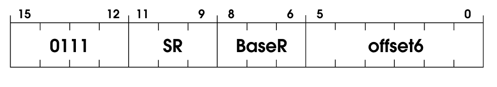
The code is also fairly simple:
pub fn str(instruction: u16, vm: &mut VM) {
    // Get the register encoded in the instruction (see `add` fn for more in-depth details)
    let dr = (instruction >> 9) & 0x7;

    // Grab the base register
    let base_reg = (instruction >> 6) & 0x7;

    // Grab the offset and sign extend it
    let offset = sign_extend(instruction & 0x3F, 6);

    // Get the value in the base_register and sum it to the offset encoded in the instruction
    // Note that we're doing some conversions here to prevent overflow.
    let val: u32 = vm.registers.get(base_reg) as u32 + offset as u32;
    let val: u16 = val as u16;
    vm.write_memory(val as usize, vm.registers.get(dr));
}
And that’s it! We’ve implemented all the operations from the spec, and we can now run more complex programs.
However, we will need to add more IO control stuff to our VM, like handling keyboard input and such. Let’s do that!
Memory-mapped registers
It’s common to create special registers to interact with peripherals, like a keyboard and mouse. These registers are only accessed by reading and writing from a reserved memory location.
In LC-3, we have two of those special memory-mapped registers:
pub enum MemoryMappedReg {
    // Keyboard status: The KBSR indicates whether a key has been pressed
    Kbsr = 0xFE00,

    // Keyboard data: The KBDR identifies which key was pressed
    Kbdr = 0xFE02,
}
One for keyboard status (i.e., is key pressed?) and another for keyboard data (i.e., which key pressed?). Why not just use getc to get this information? I like Justin Meiners’s explanation about it:
Although you can request keyboard input using
GETC, this blocks execution until input is received.KBSRandKBDRallows you to poll the state of the device and continue execution, so the program can stay responsive while waiting for input.
Okay, so when do we read/write from/to these registers? Simple enough, whenever we’re reading the VM’s memory, we will perform this check. That means we’ll be extending our read_memory function from the beginning, which was:
pub fn read_memory(&mut self, address: u16) -> u16 {
    self.memory[address as usize]
}
And it will become this:
pub fn read_memory(&mut self, address: u16) -> u16 {
    if address == MemoryMappedReg::Kbsr as u16 {
        self.handle_keyboard();
    }
    self.memory[address as usize]
}

fn handle_keyboard(&mut self) {
    let mut buffer = [0; 1];
    std::io::stdin().read_exact(&mut buffer).unwrap();
    if buffer[0] != 0 {
        self.write_memory(MemoryMappedReg::Kbsr as usize, 1 << 15);
        self.write_memory(MemoryMappedReg::Kbdr as usize, buffer[0] as u16);
    } else {
        self.write_memory(MemoryMappedReg::Kbsr as usize, 0)
    }
}
So, if the address we’re reading is the address of the keyboard status register, we’ll enter this “keyboard handling mode,” where we’ll write the status and the keyboard data to these special registers.
With that done, we can now even run a game called Rogue in our LC-3 VM:

The compiled object for the Rogue program is inside examples/ in this project’s repository. To run it: cargo run -- examples/rogue.obj.
Where to go from here
We have a working Virtual Machine for the LC-3 computer, that’s awesome. We’re able to run any compiled program that’s supposed to run on LC-3 on our VM—This is super powerful!
However, we have one problem: we depend on compiled programs to do stuff with our VM. It would be nice to write LC-3 assembly in plaintext and compile it to the LC-3 architecture. This is something I’d like to work on at some point as a continuation of this project—that and a disassembler, i.e., from the compiled .obj files to plaintext assembly.
I might work on that if I have the time and do another write-up that would be a follow-up to this one.